

BUILD PROCESS
From Modeling to the Actual Build
Designing something alone does not mean it must also be built alone. I researched the structure, developed the details, and modeled the workbench in SketchUp. Once I shared the model, WOOS evaluated whether it could actually be made and prepared it for fabrication.
This was a personal project, but it was not something I made entirely on my own.
The entire structure was designed in SketchUp. I examined the spacing of the frame, the positions of the panels and drawers, and the relationship between the catch tray and the space below from multiple angles. On screen, every component could be placed at exact coordinates, and any interference could be identified and corrected immediately.
But a model does not explain the order in which something must be built or how every connection should work in practice.
I therefore used the online engineering tool from Germany’s item24 to study different connection methods. It allows users to select profiles and connectors and assemble them in various configurations online. It would have been wonderful to place an order directly from the finished configuration, but that was not possible in Korea.
Instead, I experimented with different structures in the tool until I understood them more clearly, then returned to SketchUp and refined the design.
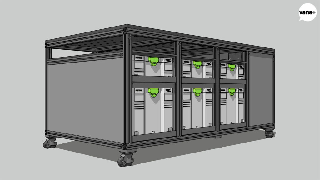
Questions such as which parts needed to be machined first, whether a tool could reach a particular fastener during assembly, and how much tolerance a panel needed in order to fit properly required practical experience.
I worked through those questions with the owner of WOOS.
WOOS is a furniture maker specializing primarily in birch-plywood furniture and loft beds. I have known its owner for many years, and despite my demanding requests, he has always produced careful, considered results. Like me, he is interested in trying new things, so whenever I begin another unusual experiment, he is willing to become actively involved. It was an exceptionally good partnership for this project.
I first met him through the Birdhouse Project in 2017. It began with my slightly strange plan to build a solid-wood birdhouse, install a Google Nest camera inside, and watch birds build a nest and live there in real time.
The process was great fun, and it became a fascinating new experience when a pair of great tits actually laid eggs and raised their young inside.
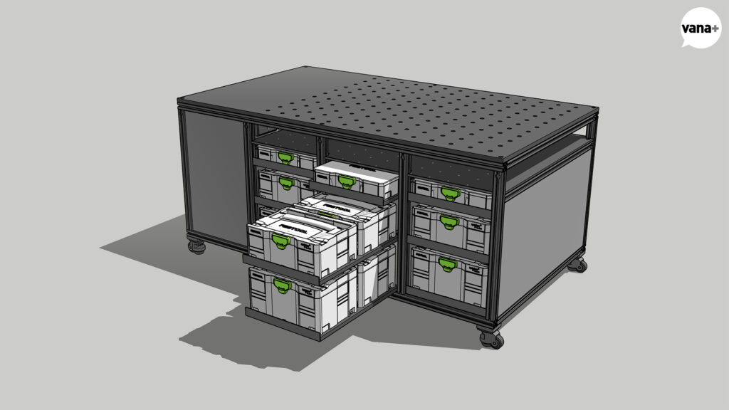
As with that earlier project, I designed the way the object would be used, its appearance, and its overall structure, while also researching the necessary information. Once the design had been reviewed, WOOS concentrated on preparing the materials, determining the machining process, and verifying that everything could actually be assembled.
It would be difficult to reduce our roles to “designer and outsourced fabricator.” I designed the use, structure, and details. WOOS translated that design into real components and a practical sequence of operations, then fabricated and tested it.
The owner of WOOS liked the design and the experiment enough to build one for his own workshop as well. As a result, two workbenches based on the same design were made together.
The machining sequence for the aluminum profiles required especially careful planning.
The profiles needed more than basic cutting and holes for fasteners. Additional openings were routed into their sides so clamps could be inserted into the slots. The freshly cut aluminum edges were extremely sharp, so every edge also needed to be softened to prevent injury.
Only after all machining had been completed could the components be sent to a separate specialist for black anodizing. If a missing operation were discovered afterward, any additional cut or hole would reveal silver aluminum again.
Before assembly, every fastening position and machining requirement therefore had to be compared against the drawings, checked, and checked once more.
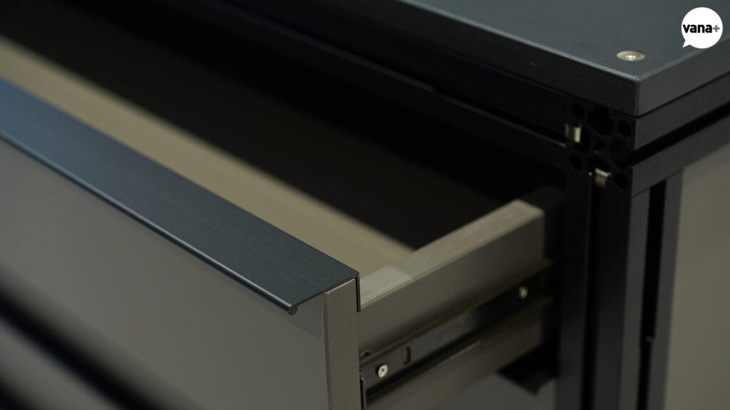
For the panels, the flatness of the top and the accuracy of the MFT holes were particularly important. The top was machined on a large CNC router according to my drawings. Several new cutting bits were prepared and replaced during the process to maintain accuracy.
The vertical panels carrying the drawer runners were also designed to sit flush behind the 40 × 40 mm aluminum profiles, so even the less visible areas would not appear unfinished. Nine-millimeter HPL-faced panels were attached to both sides of the central plywood core so that only the dark-gray surfaces would be visible from outside. Additional machining allowed the completed panels to slot into the surrounding profiles on all four sides.
The amount of plywood alone made the workbench extremely heavy. Then there were the heavy-duty aluminum profiles.
I had expected the runners to be heavy from the moment the Penn Elcom shipment arrived, but they were heavier than I had imagined. A single workbench contains fifteen Systainer trays and five general-purpose side drawers, making twenty drawers in total.
Each drawer requires a pair of runners. That means twenty pairs per workbench—or forty individual runners.
Nine pairs of 700 mm Penn Elcom runners are used for the long trays on Side A. The remaining trays and general-purpose drawers use 350 mm or 400 mm Häfele runners.
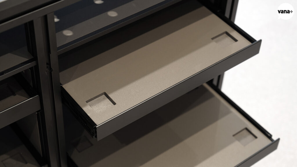
Simply placing a Systainer on a flat tray would allow it to move while being opened and closed, potentially causing it to strike the surrounding panels. I therefore machined recesses into the tray surface to match the Systainer feet and painted the exposed areas afterward.
The original tray width did not allow two Systainers placed front to back to open smoothly, so the overall width of the workbench had to be increased.
The recesses needed enough depth to locate the feet securely, while the sides of the trays also had to carry the heavy runners. This resulted in a surprisingly substantial tray. Once the Systainers and tools are added, the moving mass becomes considerable.
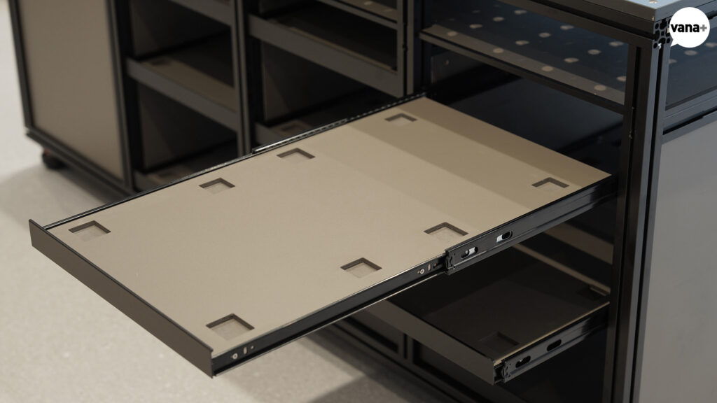
Weight was not the only challenge. Fastening the frame and aligning the drawers involved more than matching dimensions.
The height of the front handle, the thickness of the tray base, and the connection between the runner and the base may appear simple. But if any one of them were misaligned, the result could look remarkably cheap. These areas required careful details that would remain largely unseen.
Two power outlets were installed on each side beneath the top. A dedicated floor outlet had already been installed where the workbench would stand, allowing it to draw substantial power. The internal wiring was made with Dongyang 4 sq mm × 3-core flexible, matte-finish, high-capacity cable.
Because German JUNG switches and outlets were used throughout the atelier, I selected matching European square outlets from the LS 990 series for the workbench. They were installed in JUNG’s dedicated orange plastic mounting boxes rather than conventional wall boxes. Because of their exposure to dust, I chose versions with covers that could remain closed when the outlets were not in use.
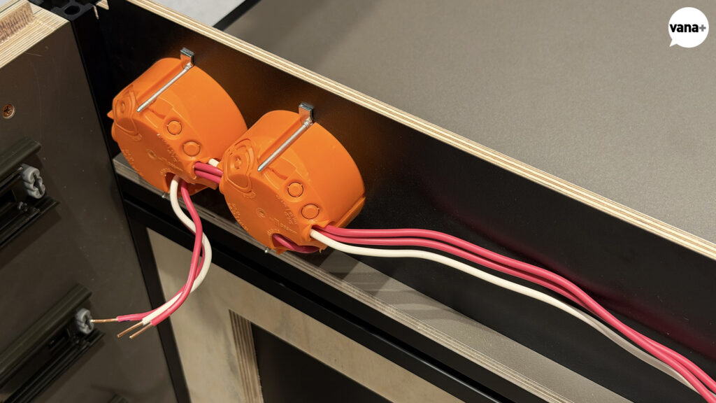
As assembly progressed, the decisions made inside the digital model began to take physical form. The dark ends of the finished profiles, the black edges of the holes in the top, the open direction of the catch tray, and the positions of the handles and runners gradually came together.
As the workbench approached completion, my first reaction was not really about its functions or design. It was a difficult, strangely unfamiliar feeling.
Something I had seen for so long only as a model on a monitor was now standing in a real space. At the same time, I could finally experience a sense of weight and solidity that no screen could communicate.
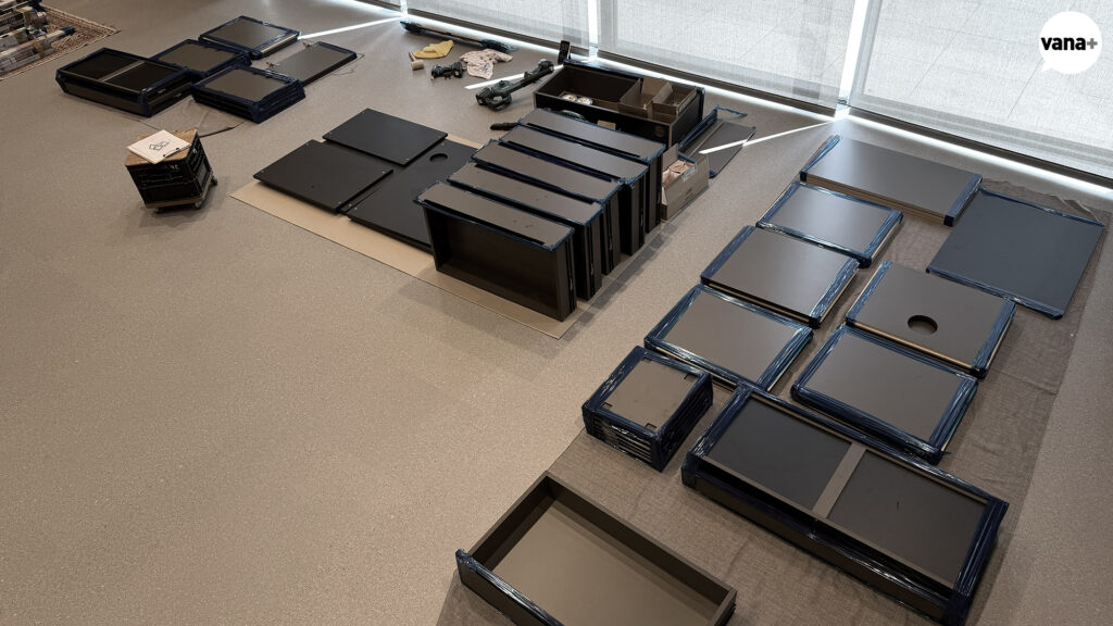
Installation at the atelier took place over two days. This does not mean that installing a single MFT workbench required two full days. I had woodworking classes in the mornings and could only begin in the afternoons. We were also installing the smaller workbenches for the other machines, so the process naturally extended into a second day.
Nothing especially dramatic happened. But as several workbenches found their places at once, the atelier’s working area finally began to resemble the space I had imagined.
MAKING SEQUENCE
- Define the required functions and Systainer-storage plan
- Model the frame and storage in SketchUp
- Review manufacturability with WOOS
- Cut and machine the aluminum profiles, handles, and finishing channels
- Black-anodize all machined components
- Machine the HPL panels and MFT worktop
- Test-assemble the frame, review the structure, and verify detailed dimensions
- Install the runners on the side panels
- Install the catch tray, handles, and power components
- Assemble the worktop, casters, and finishing components
- Fully secure the finished structure and assemble the drawers
- Align, inspect, and clean
The Completed Workbench and Its First Module