

FUNCTION & LAYOUT
Functions and Structures Shaped Around the Way I Work
It is not difficult to make a long list of features. The difficult part is fitting them into the same space without allowing them to interfere with one another.
I needed a catch tray beneath the top, and below that I wanted to fit as many Systainers as possible. The power outlets also needed to be close at hand without being visually intrusive.
When I began designing the bench, the first thing I did was not draw its exterior. Instead, I wrote down the actions I repeatedly perform while working.
Secure a workpiece to the top. Take a tool out of a Systainer. Put a clamp down for a moment. Plug in a power tool. Take measuring instruments such as a square, vernier caliper, or marking gauge in and out of a drawer. Slide parts being assembled beneath the bench. Attach a light above the work surface. Mount clamps to the sides, and insert bench dogs or lever clamps into the MFT holes. And so on.
The design was guided by the goal of making these actions flow as naturally as possible.
The top was planned as a large MFT perforated surface. This was not solely for using Festool accessories. A consistent hole pattern could serve as a common interface not only for clamping and guides, but also for accessories I might design and make in the future.
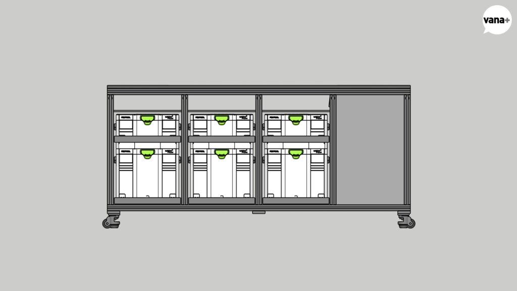
Directly beneath the top, I placed a catch tray. Its primary purpose was to preserve enough open space to reach the underside of the work surface when installing clamps and other accessories that use the MFT holes.
It would also allow electrically powered accessories to be connected without cables running across the top. If I were to use something like TrackTubes’ The Original VACUDOG™, which I am currently considering, a vacuum line could be connected from below to secure a workpiece on the surface.
As a secondary function, it provides somewhere to slide long workpieces or tools before putting them away properly. Three sides remain open, apart from the side containing the power outlets, making the tray easy to access. There is no raised lip at its opening, so objects can be slid in without obstruction.
Because everything stored there is concealed by the top, the space does not look untidy either. It may appear to be a simple shelf, but I expected it to become one of the most frequently used features for keeping interruptions in the workflow to a minimum.
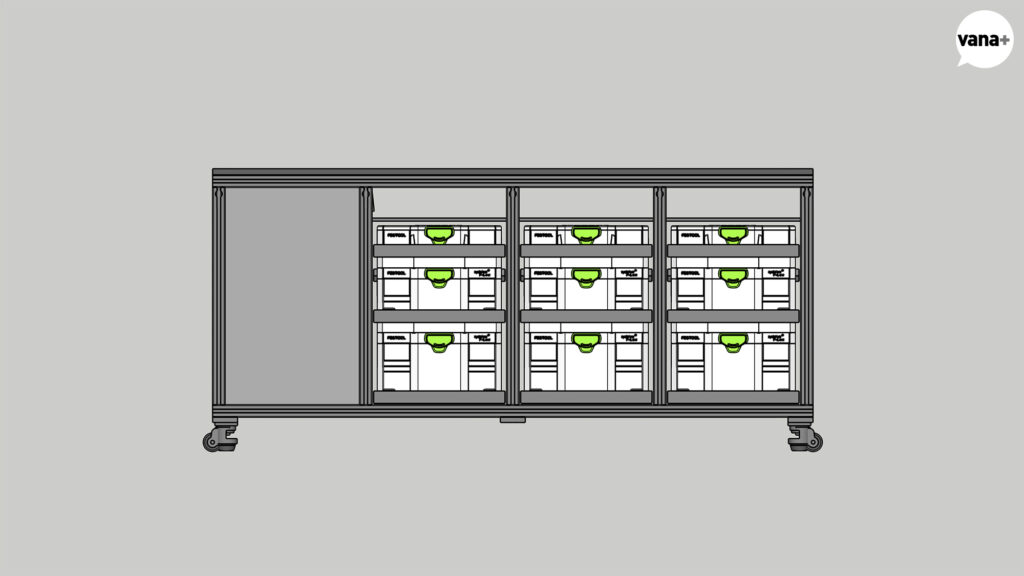
Farther down is the storage area for the Systainers.
Taking a cue from The Garage Journal’s workbench, I did not make both sides identical. One side has long trays that hold two rows of Systainers, front and back. The other has shallower, single-row storage designed for easier access. From the outside, the bench appears nearly symmetrical, but its interior is asymmetrical according to how it will be used.
Systainers are already designed for compact storage. If I had placed only one on each side, the width of the top would have become considerably narrower as well. I interpreted The Garage Journal’s configuration as a way to retain both storage capacity and a generous work surface.
Even apart from the size of the top, varying the depth and method of access according to the direction from which tools are most frequently retrieved seemed more useful in practice than filling every side in exactly the same way.
The storage capacity and height were determined according to the Systainers I already owned.
- Side A: SYS3 M 89 × 6, SYS3 M 187 × 6, SYS3 M 237 × 6
- Side B: SYS3 M 187 × 3, SYS3 M 337 × 3
Side A consists of nine trays, each holding two Systainers in front-and-back rows. Side B has six trays, each holding one Systainer. This gives the workbench fifteen Systainer trays in total, with a planned capacity of twenty-four Systainers. Adding the five general-purpose drawers on the side brings the total number of drawers in a single workbench to twenty.
The six 89 mm-high organizers are intended for sorting small parts into separate containers so they can be found and used easily. The 337 mm-high drawer-style SORTAINERS are positioned so they can be opened and used directly from the front of the bench.
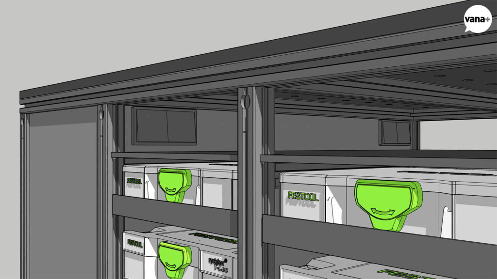
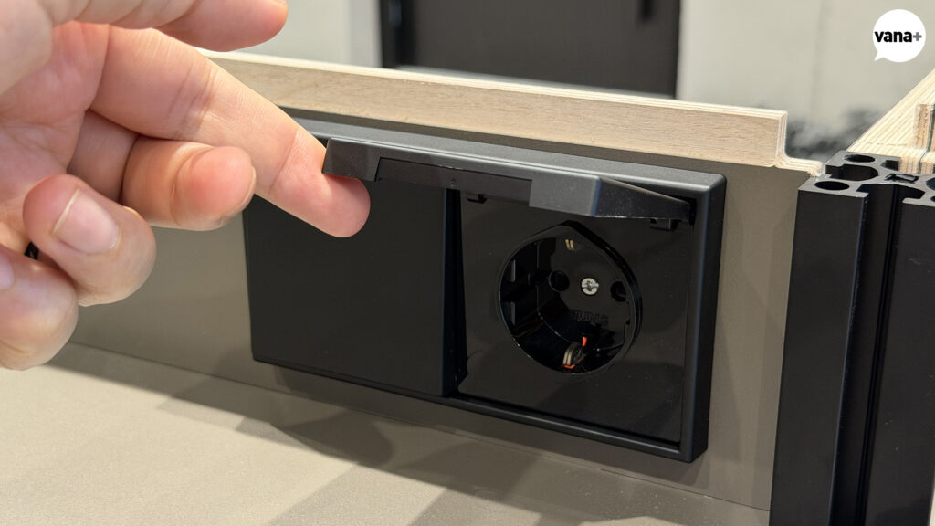
Because this is a modern workbench, power tools will be connected to it frequently. The outlets therefore needed to sit close to the top while remaining as hidden as possible during normal use.
I placed two outlets on each of the inner walls below the work surface, making four in total. Covered outlets were chosen to cope with the airborne dust and sawdust that are unavoidable in woodworking, while the cables were routed inside the structure. The outlets remain close and convenient without being visually exposed on the front of the bench.
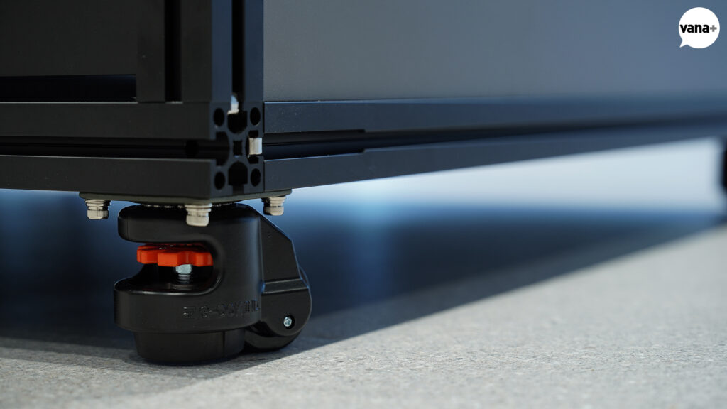
With far more aluminum profile and thick plywood than one might expect, this is a substantial and extremely heavy workbench. It is unlikely to be moved around very often. Even so, I did not want it to be permanently fixed in a single position within the atelier, so mobility was considered from the beginning.
At the same time, the bench needed to remain completely stable when hammering, chiseling, or sawing on its surface. I therefore installed heavy-duty leveling casters at all four corners, allowing the height to be adjusted and the bench to be fully stabilized.
In the final configuration, I added one leveling foot between each pair of casters to support the structure against any possible bending of the aluminum profiles.
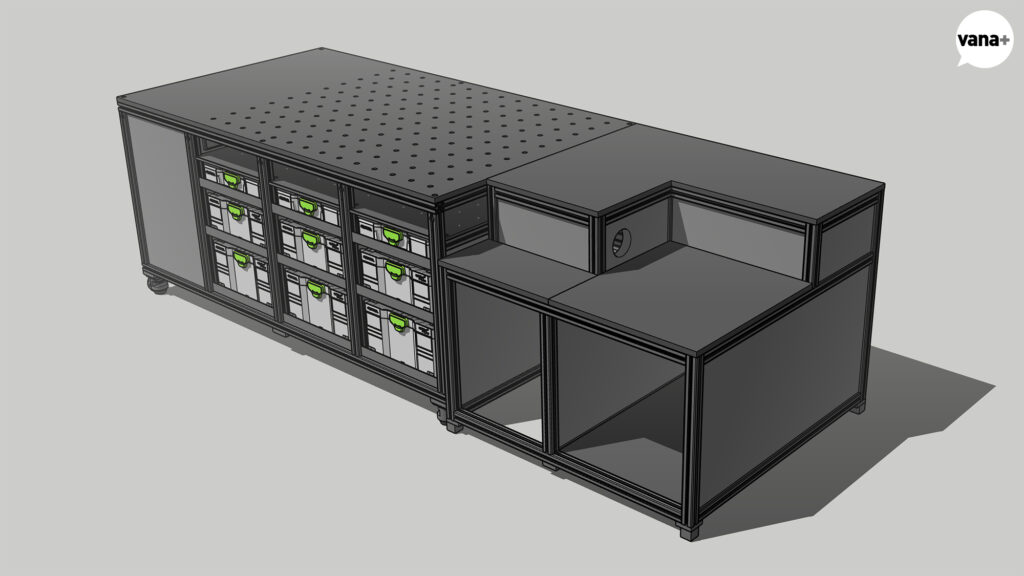
The final design criterion was another workbench that did not yet exist.
The modules I am currently considering are a Saw Bench for the Festool CSC SYS 50 table saw and a separate Router Table. The goal is not simply to maintain the same visual concept. The work surface of the table saw will be aligned precisely with the top of this MFT workbench so that the latter can serve as an extension table.
Because the modules need to connect naturally while remaining securely fixed, I decided not to rush into building them at the same time. Instead, I postponed them until the next stage.
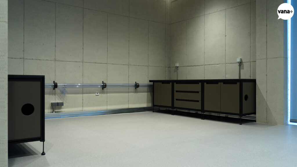
Smaller workbenches for a compact JET sander, a benchtop drill press, and a Laguna wood lathe were built at the same time and installed in the atelier. These pieces were also based on the same general concept.
In the end, the form of this workbench emerged from the flow of the work rather than from styling. Once the heights of the top, catch tray, drawers, power system, and lower frame had been determined in sequence, much of its outward appearance followed naturally.
Material Selection and a Black Finish