

DUCTWORK & LAYOUT
DUCT SIZES AND ROUTING
The only thing left was to create the path through which the air would actually travel.
The dust collection ductwork.
I had spent a considerable amount of time deciding where the dust collector should be placed and how it would be controlled. Yet I knew virtually nothing about the pipes that would connect it to each woodworking machine.
So once again, I decided to begin by studying the basic principles.
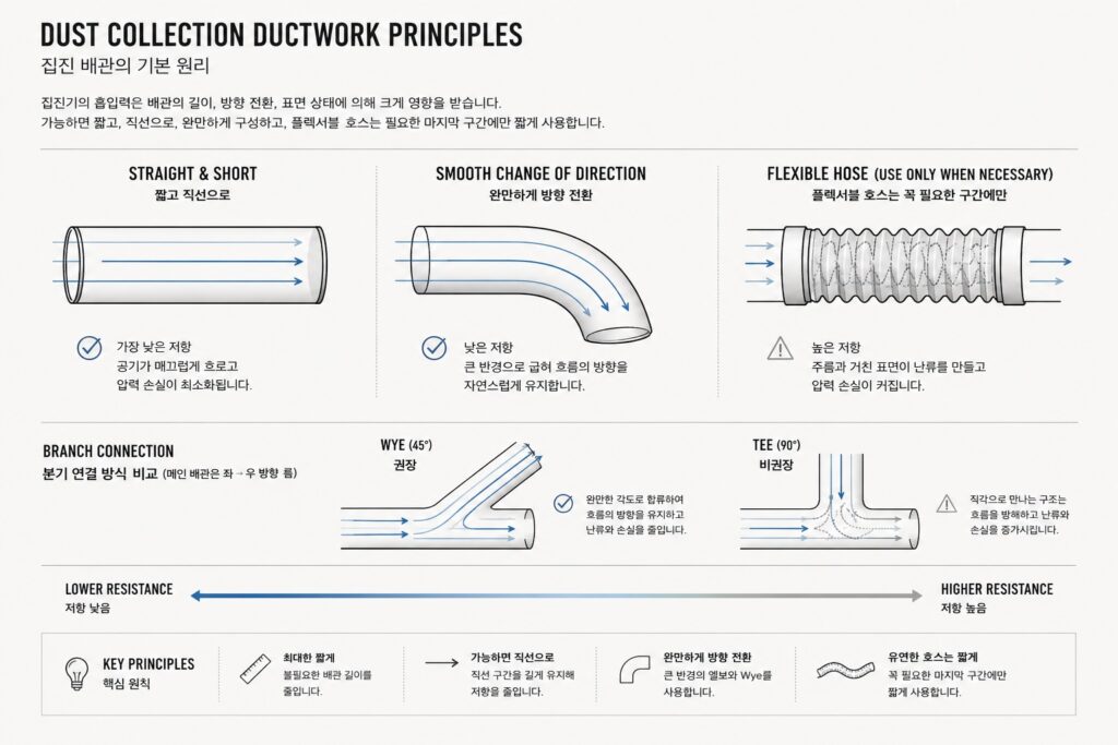
No matter how powerful the dust collector may be, resistance inevitably increases as the duct becomes longer, narrower, or changes direction more abruptly.
In the end, the important principles were simpler than I had expected.
- Keep it as short as possible.
- Keep it as straight as possible.
- When a change in direction is unavoidable, make it as gradual as possible.
- And use Flexible Hose—with its bends and uneven interior surface—only for the short final section where it is absolutely necessary.
I had not uncovered any extraordinary principle, but most of the decisions that followed began with these basic rules.
Connecting several machines to a single dust collector naturally requires the ductwork to branch at several points.
Knowing nothing about ductwork, I initially thought it would be as simple as dividing the line with a Y-shaped connector.
I had at least assumed that a Y-shaped fitting would interfere with the airflow less than a T-shaped one.
But as I researched dust collection ductwork, I found that systems with a directional airflow generally use something closer to a lowercase “y” than a symmetrical capital “Y.” One branch joins the main duct at an angle while preserving the direction of the main airflow.
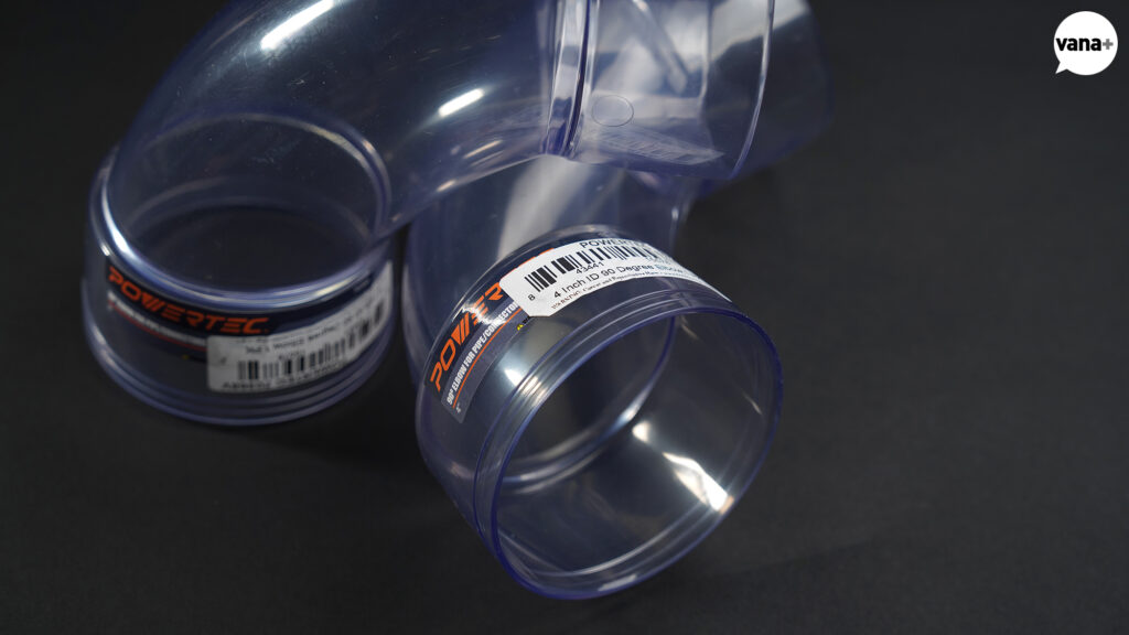
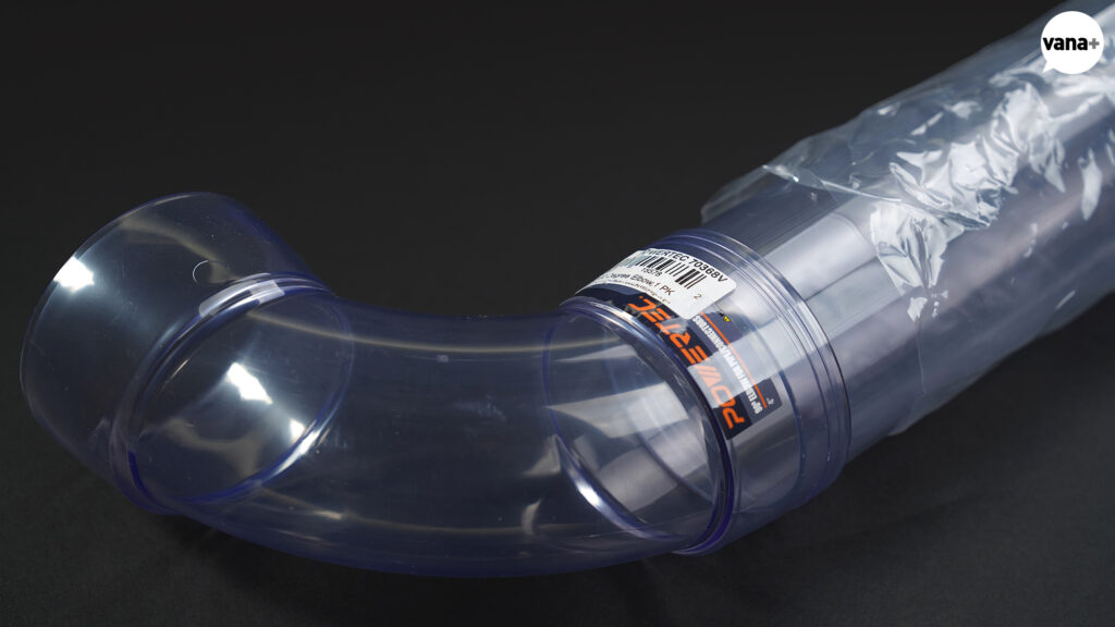
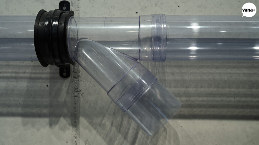
Each one was oriented upward or downward according to the position of the dust port on the corresponding woodworking machine.
Air and sawdust move through the duct at high speed toward the dust collector. If their direction changes abruptly at a junction, turbulence and resistance increase accordingly. A branch that meets the main duct at a gentle angle, however, can merge into the airflow without forcing it to make a sudden turn.
For this reason, woodworking dust collection systems commonly use Wye fittings, in which a branch joins at a gradual angle of about 45 degrees, rather than right-angle Tees or symmetrical Y-shaped fittings.
After learning this, I began looking for y-shaped connectors to purchase. Most suppliers categorized the shape I wanted as a “Wye Fitting.”
At first, I assumed that “Wye” was simply a name used to distinguish the lowercase-y shape from a capital Y. I later discovered that this was not particularly the case.
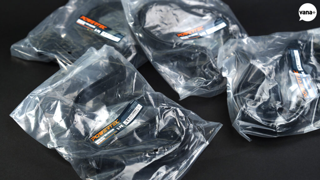
As I searched for the various fittings I needed, their names gradually became familiar.
A fitting that changes direction is an Elbow. One that branches at a right angle is a Tee. A gradual branch is a Wye. A fitting that connects ducts of different diameters is a Reducer.
Not knowing the names would not necessarily prevent me from connecting the ductwork, but at least I now knew what to search for.
Then, as I began ordering the actual components, I encountered another problem I had not anticipated.
Pipe sizes.
Ah. Apparently, nothing about this was going to be easy.
During the construction of the atelier, I had installed 100A VG2 PVC Pipe from the basement dust collection room to the first floor. This is a standard commonly used in Korea.
Dust collection systems for woodworking machines, on the other hand, are dominated by North American products, most of whichlsom using a 4-inch standard.
100mm and 4 inches.
Converted to millimeters, 4 inches is 101.6mm.
That seemed close enough to be essentially the same size.
It was not.
(Could the world not agree on a common standard for something as basic as pipe?)
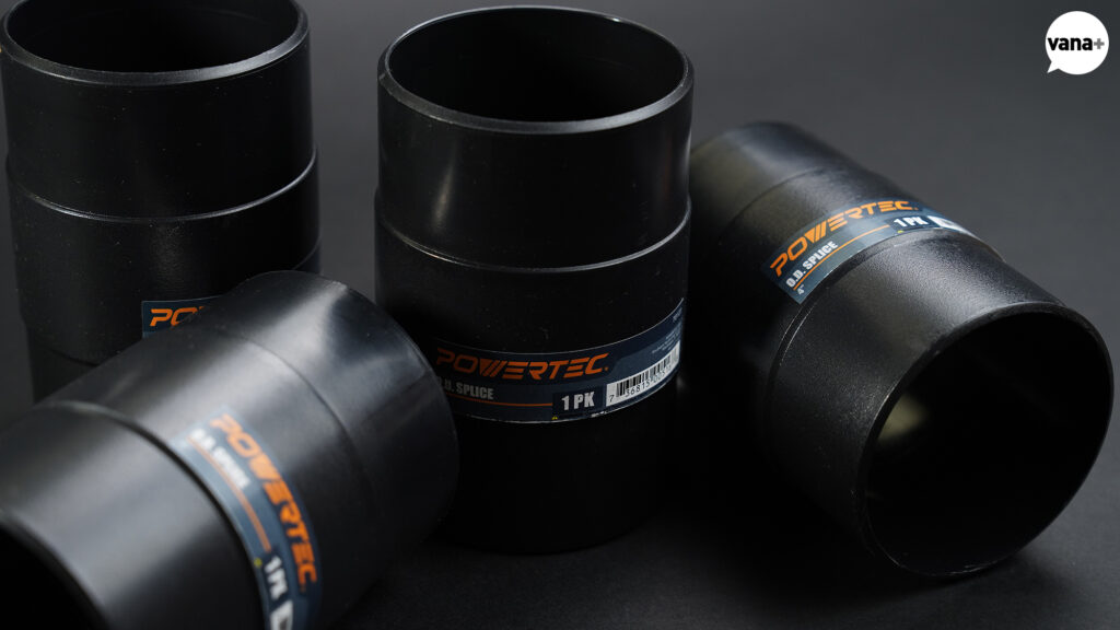
The 100A VG2 Pipe installed in the building has an Outer Diameter of approximately 114mm.
The POWERTEC 4″ dust collection pipe I purchased, however, measures roughly 100mm across its outside diameter.
The difference is almost 14mm.
I was about to blame the North American imperial system again, but it turned out that this was not the only issue.
Pipes use a concept called Nominal Size, which means that the number in a product name does not necessarily correspond directly to its actual inner or outer diameter.
To make matters more confusing, dust collection hoses, dust collection pipes, and plumbing PVC may be specified according to either their Inner Diameter or Outer Diameter, depending on the product.
The conclusion was simple.
Never trust a pipe by its name.
The actual inner and outer diameters of every product being connected must be checked individually and carefully.
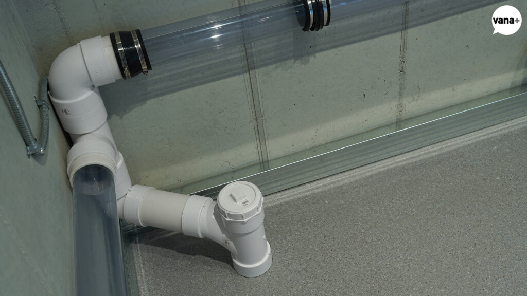
I could not tear out the 100A pipe already embedded in the building. At the same time, adapting every North American dust collection accessory I might use in the future to Korean pipe sizes did not seem like a sensible long-term solution.
So I decided not to force the entire system into a single standard.
The sections belonging to the building would use the Korean 100A standard.
The dust collection system inside the workshop, where the woodworking machines would be connected, would use the North American 4″ standard.
A Reducer would connect the 100A and 4″ systems at the boundary between them.
Thinking about it again, this was probably the simplest solution.
The 100A VG2 duct rising from the basement could continue through the Main Intake to the point where it splits toward the two groups of woodworking machines. Everything after that point could be standardized as a 4″ dust collection system.
That would also allow commonly available North American 4″ products to be used directly whenever machines or accessories were added later.
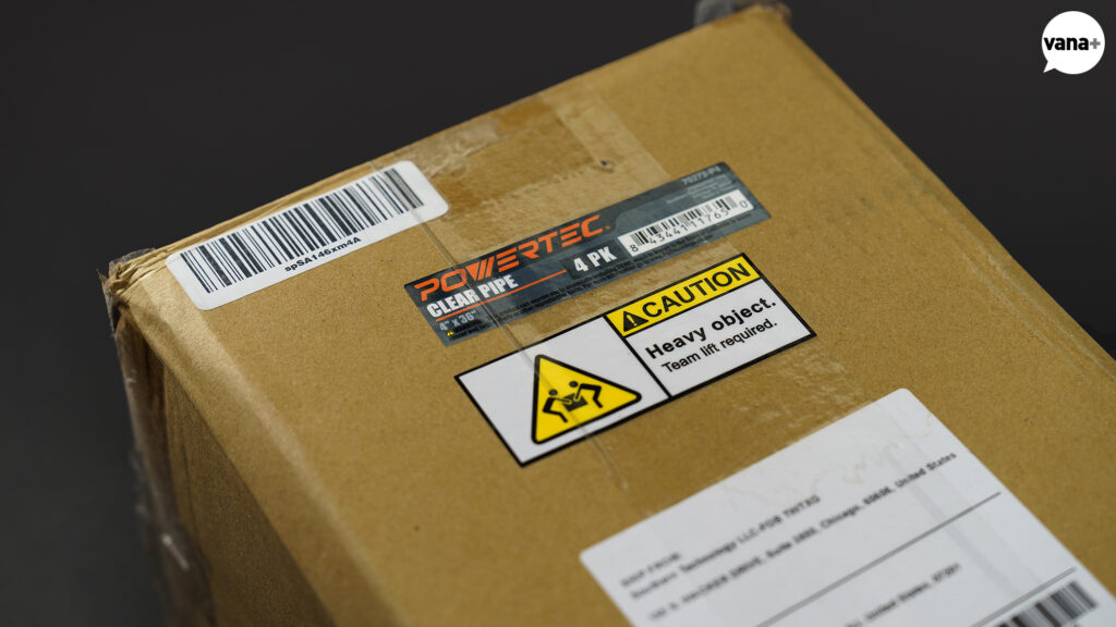
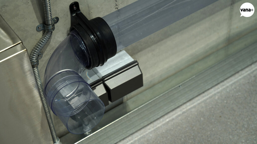
For the main ductwork inside the workshop, I selected POWERTEC 4″ Clear PVC Pipe.
It is a rigid, transparent PVC pipe supplied in 36-inch lengths.
The main reason for choosing transparent ductwork was to make blockages easy to identify visually.
Woodworking does not produce only finely milled sawdust of a consistent size. Larger pieces of wood and other small objects can also be drawn into the system.
If an opaque duct became blocked, I would have to disconnect it section by section to locate the problem. With a transparent pipe, I could immediately see at least where the blockage had occurred. It would even be possible to judge, to some extent, whether the dust collection was working properly simply by watching the material move through the pipe.
And honestly, I also liked the way it looked.
Watching sawdust rush through the clear pipe should be interesting, and neatly aligned ductwork on the wall would ultimately become part of the interior design.
If the ductwork could not be hidden, I would rather display it properly.
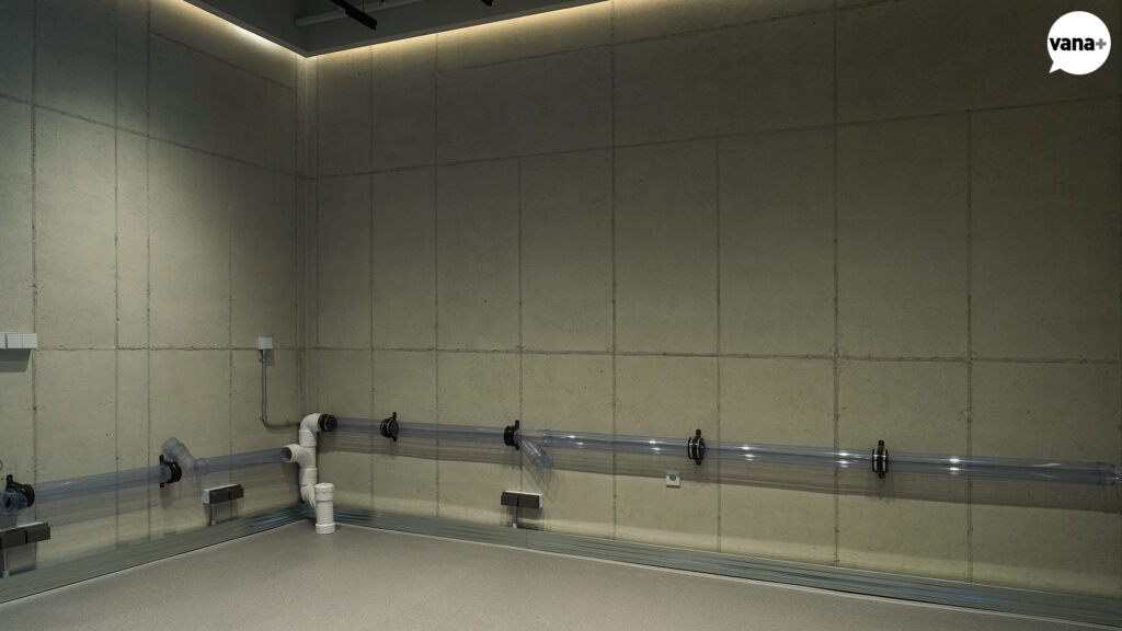
The different sizes and materials are clearly divided.
For better collection efficiency, I decided to use Rigid Pipe for as much of the main system as possible and reserve Flexible Hose for only the final connection to each machine.
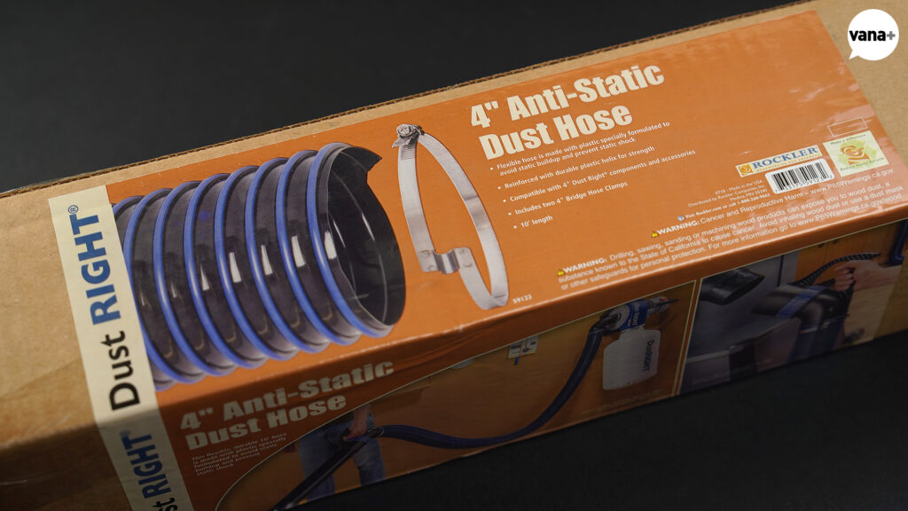
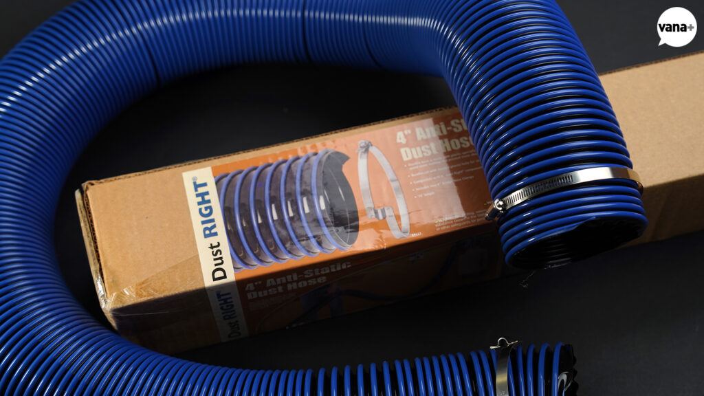
Rigid Pipe has a smooth interior and maintains a consistent shape. Corrugated Flexible Hose creates considerably more resistance to airflow. But connecting everything with rigid pipe would not be practical either.
A machine may need to be moved slightly for maintenance, and the position and direction of the dust port vary from one machine to another. The final connection therefore needs enough freedom to move within a limited area.
Flexible Hose also has another possible advantage. If a large object is briefly drawn in and blocks an inlet rather than causing a problem elsewhere in the system, a fixed pipe may require a long tool to push the obstruction through or break it loose. A flexible hose can simply be lifted and shaken out.
I therefore decided to use POWERTEC Clear PVC Pipe from the Main Intake through every branch leading toward the woodworking machines. For the short section between each Blast Gate and its machine, I would use Rockler 4″ Dust Right Anti-Static Flexible Hose.
Rigid and Flexible would each have a clearly defined role.
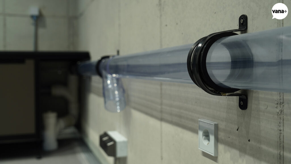
Most of the duct positions had already been determined while planning the machine layout.
The duct would rise from the Main Intake, divide to the left and right, and continue along the walls to each machine. Because the ductwork would be installed visibly on the wall, alignment was as important as function.
I planned to establish reference lines with a laser level and keep every section as vertical or horizontal as possible.
In front of each machine, a Wye or Elbow would establish the direction. The line would then pass through an iVAC Motorized Blast Gate and connect to the machine with a short Flexible Hose.
From the perspective of the wood dust, the flow can be summarized as:
Woodworking Machine
↓
Rockler 4″ Anti-Static Flexible Hose
↓
iVAC Motorized Blast Gate
↓
POWERTEC 4″ Wye / Elbow
↓
POWERTEC 4″ Clear Rigid Pipe
↓
100A → 4″ Reducer
↓
100A VG2 PVC Pipe
↓
B1F Dust Collector
That is the basic structure.
Written down, it occupies only a few lines. I have no idea how many product pages and ducting references I had to examine to decide on it.
Of course, not every machine could be completed by simply attaching a hose to the end of the duct.
Machines with clearly defined dust ports, such as the Band Saw, Jointer, and Planer, were relatively straightforward.
(The Band Saw I purchased actually has two dust outlets, so combining those two connections remains another task.)
The more ambiguous machine was the Wood Lathe.
The biggest problem was that I had never actually used one and did not yet understand its operation particularly well.
I bought it because I was interested in woodturning, and that interest led me to watch a great many videos on YouTube. But unlike other woodworking machines, the workpiece itself rotates on a lathe and the cutting position continually changes. This makes it impossible to fix the dust inlet permanently in one position.
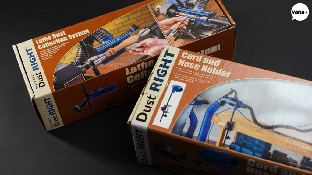
For this machine, I decided to use Rockler’s Dust Right Lathe Dust Collection System.
Its dust hood can be repositioned according to the work, allowing it to be placed as close as possible behind the lathe.
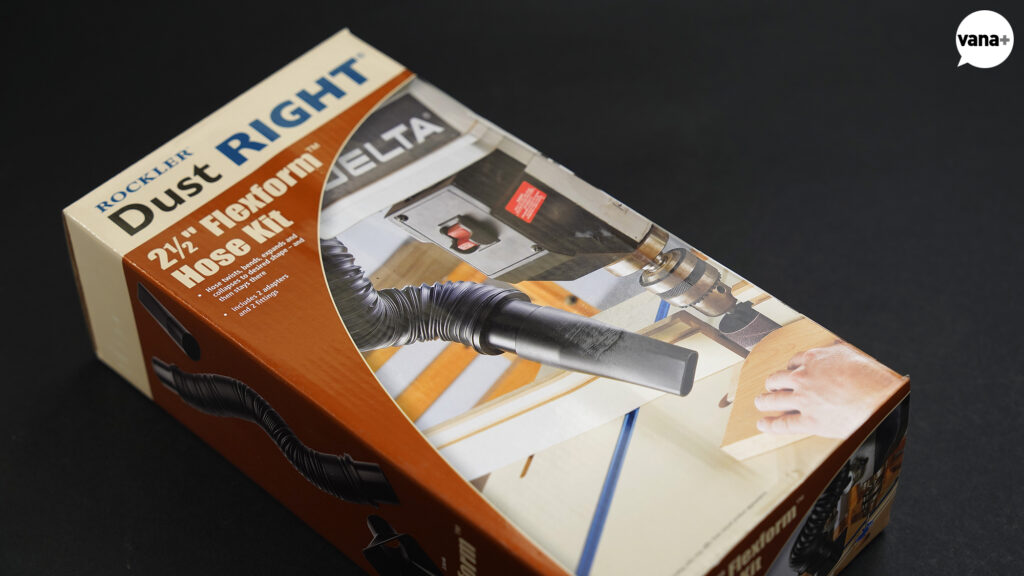
For machines used on a workbench, I also prepared accessories such as the Dust Right Cord and Hose Holder so that the hose position could be adjusted as needed.
Rather than forcing the entire duct system into a single method, it seemed far more practical to adapt the final few dozen centimeters to the way each machine would actually be used.
The components prepared for connecting the machines were ultimately as follows:
POWERTEC 4″ Clear PVC Pipe 36″ × 10
POWERTEC 4″ Wye × 3
POWERTEC 4″ Elbow × 3
Rockler Dust Right 4″ Anti-Static Flexible Hose × 5
Rockler Dust Right Lathe Dust Collection System
Rockler Dust Right Cord and Hose Holder
Rockler Dust Right Mountable Dust Coupler × 2
Rockler Dust Right Flared Quick Coupler, 4” Port to 2-1/2” Hose
Rockler Dust Right Flared Quick Coupler, 4” Port to 4” Hose × 2
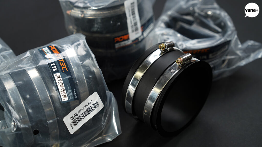
Rockler Dust Right 4” Rubber Union for Dust Collection × 3
Rockler Dust Right Schedule 40 PVC Adapter, 4” PVC to 4” Hose × 3
Rockler Dust Right 2-1/2” FlexForm™ Hose Kit
Rockler 4” Keyed Bridge Hose Clamps, Pack of 5 × 5
The following components were used for the building-side ductwork:
100A VG2 PVC Pipe
100A Wye × 2
100A Cleaning Cap
If a problem occurred in the building-side duct between the Main Intake and the dust collector, resolving it would be extremely difficult. I therefore added a separate Cleanout at an accessible location.
Finally, the two standards would be connected using:
100A VG2 → 4″ Dust Collection Pipe Reducer × 2
I initially thought this would require only a few pipes and hoses. Gathered together, however, the list became quite substantial.
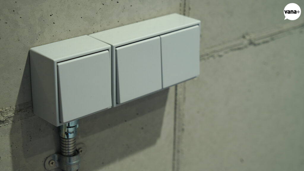
A covered JUNG outlet is installed above.
With that, most of the preparation for the dust collection system was complete.
The dust collector had been moved out of the workspace.
iVAC would allow the woodworking machines, Blast Gates, and dust collector to operate together automatically.
A Raspberry Pi Dashboard would show the status of the dust collector hidden from view.
Finally, the ductwork would provide the path for air to travel from each machine to the collector.
At each machine location, a dust-resistant outlet connected directly to its own circuit breaker was installed at a low level. Covered JUNG outlets were positioned above for equipment that would be connected temporarily, offering additional protection from airborne wood dust.
Of course, it was still a little early to call the system finished.
The actual control circuit connecting the Laguna C|Flux:3 to the iVAC MSC still needed to be verified. The RUN signal confirming that the dust collector was physically operating also needed to be connected to the Dashboard.
And although the ductwork had reached the position of each machine, the machines themselves had not yet been connected.
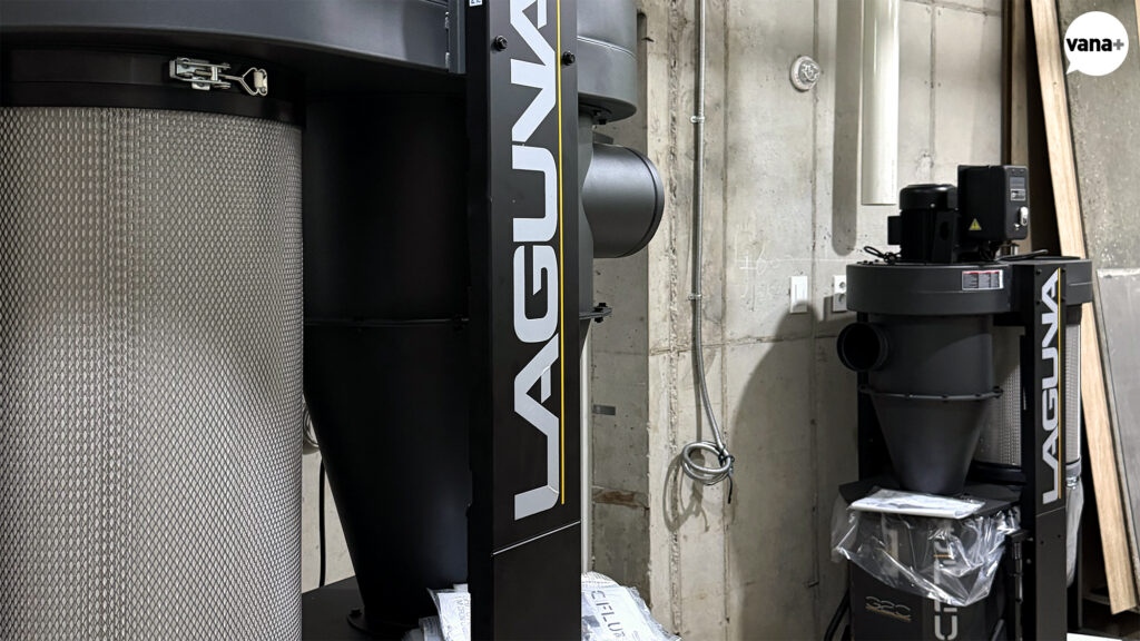
I will not know whether everything truly works until all the electrical connections are completed, every machine is fixed in its intended position, and the system is operated for real.
No matter how much research went into it, or how carefully I planned it, unexpected problems will inevitably appear once the system begins drawing in actual sawdust.
Which machine will not receive enough suction?
Where will sawdust begin to accumulate?
Will the gates and automation operate as intended?
Will the Dashboard display the correct status?
Those are no longer questions that can be answered by sitting at a desk and thinking about them.
For now, I have completed everything that could be prepared in advance.
The rest will have to be discovered one step at a time through actual use.
Return to all project notes